|
CASH-Interface2 v1.35 Universal CASH Interface 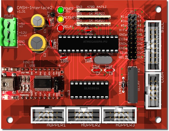
Features - Simultaneous operation of a coin and bill validator as well as 3x hopper. - Connection of cashless systems via PULSE interface. - PC connection via USB port. - The interface is monitoring six channels + power supply. Using BINARY Mode there are 15 different bills and 31 different coins possible at the same time. - The devices are disabled until the software activates them (Totalblocking / Inhibit). - The pinning of the connectors are designed for coin acceptors of the type NRI G13 - RM5 - EMP 800 - EMP 850 - Microcoin SP/QL - MEI CASHFLOW 330 - MONEY CONTROLS C120, CONTROLS C120, and for bill acceptors of the type NV9 or NV10. We offer also specially wired connection cables or adapters for all other types, e.g. NRI G40 or GBA ST2. - External coin sorter control via hopper full signal (SRT / H-FULL jumper). - Hopper full and empty signal detection. - 2 free usable inputs, e.g. to connect push buttons. - 2 free usable outputs, e.g. to connect lamps or other actuators. 1 output as relay contact. - Watchdog function, that means the acceptance is deactivated on errors. - The control of the devices is done with simple commands, or by the free available CASH-Interface2 software. Supported devices Coin validator of the type: RM5, NRI G13/G18, NRI G40, EMP 800, EMP 850, MARS, MONEY CONTROLS C120, AZKOYEN, FAGE, ICT Bill validator of the type: NV9, NV10, GBA HR1, GBA ST2, JCM, MEI, APEX, MATRIX, VECTOR You can connect every coin and bill validator supporting PARALLEL, PULSE or BINARY mode. Other interfaces like ccTalk or MDB are not supported! Hoppers of the type: Universal Hopper MK2, MK3 and MK4, Azkoyen U-II Hopper, Flow Hopper, NRI H2 Hopper, Cube Hopper MK2 intelligent, Evolution Hopper, Escendo Escalator Hopper, Excel Hopper, Rode-U-Hopper, or others that support the PULSE mode. Bill dispenser of the type: ICT ND-300 , ICT CVD-300 or other that support the HOPPER / PULSE mode. You can connect every hopper or bill dispenser supporting PULSE mode. Connection Connect the CASH-Interface2 to the PC using a USB cable. Supply the CASH-Interface2 board with a voltage of 12V DC. Ensure that the plus and minus pole are connected correctly! Be sure to take the precaution of making sure the power supply is strong enough. A bill validator can take up to 1500 mA and a coin acceptor up to 500 mA of current. A hopper can take up to 3A and more! USB driver Normally the USB driver is installed by Windows automatically when the CASH-Interface2 is plugged in the very first time. The CASH-Interface2 works with the latest FTDI driver v2.12.36.20 The driver is available for download here: CASH-Interface2 FTDI USB driver 32+64Bit The used COM port number is displayed in the Windows device manager, see Ports (COM & LPT). Coin validator connection The connection of the coin acceptor (e.g. NRI G13) is made by a 10 pole flat ribbon cable to the plug marked with COIN. The operating mode for coin acceptor can be PARALLEL, BINARY or PULSE interface. Occupation of the 10 pole plug (NRI G13 compatible): 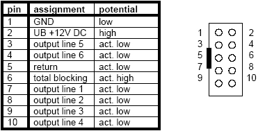
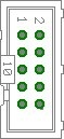
Bill validator connection The connection of the bill validator (e.g. NV7/8/9/10) is made by a 16 pole flat ribbon cable to the plug marked with BILL. The operating mode for bill acceptor can be PARALLEL, BINARY or PULSE interface. Occupation of the 16 pole plug (NV7/8/9/10 compatible):
If you want to connect a other bill validator than NV9 or NV10 you need to assemble a adapter cable with the above occupancy. Hopper connection The connection of a hopper or bill dispenser is made by a 10 pole flat ribbon cable to the plug marked with HOPPER1, HOPPER2 or HOPPER3. The operating mode for hopper should be PULSE interface. Occupation of the 10 pole plug (Azkoyen compatible):
If you want to connect other devices than Azkoyen or Suzohapp Flow Hopper you need to assemble a adapter cable with the above occupancy or use one of our adapter boards. We offer adapters for MK4 hopper and ND-300 bill dispenser. 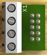 Our ND-300 bill dispenser adapter can be plugged into the CASH-Interface2 HOPPER connector. It offers the hopper’s motor run pin (OUT) and empty sensor (IN) so you can connect easily a ND-300 bill dispenser and use it in hopper mode.
The adapter can also be used to have an extra INPUT and OUTPUT for the CASH-Interface2 if there is no hopper connected. For example we use this for the photo booth control to have external illuminated push buttons. Hint: The output can switch a maximum current of 500 mA, on more load you have to connect a relays between load and output. Connection of an illuminated push button on the HOPPER plug via ND-300 adapter: 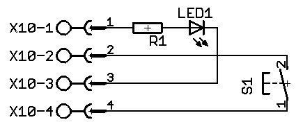
Cashless systems connection The CASH-Interface2 supports the connection of cashless devices via PULSE-Interface. To do this, simply connect the PULSE output of the cashless device to a channel, e.g. COIN #1 - #6. We offer a PULSE-Adapter for easy connection, see PULSE-Adapter Currently the following credit and smartcard systems can be connected: - Nayax cashless payments vpos => Instructions in PDF format: CASH-Interface2 Nayax Connection - Ingenico pos solutions smart pos self-service - CCV InSync - Otiglobal cashless payment systems otipulse - Sacoa Debit Card, POS and Redemption System - USA Technologies ePort G9 and ePort G10-S Devices settings For simultaneous operation of coin and bill acceptor we suggest this configuration: Bill validator and coin validator in BINARY mode. You have to adjust the channels of coin and bill validator accordingly. You can get the software and cable to reprogram the respective device from the manufacturer, or just choose the desired channel occupancy with your order. Example bill and coin validator (bill validator BINARY mode, coin validator BINARY mode): Channel 1-4 = bill validator binary coded value (up to 15 different bills) Channel 1 (1) = bill validator 5 Euro bill Channel 2 (2) = bill validator 10 Euro bill Channel 3 (1+2) = bill validator 20 Euro bill Channel 4 (3) = bill validator 50 Euro bill Channel 5 (1+3) = bill validator 100 Euro bill Channel 6 (2+3) = bill validator 200 Euro bill Channel 7 (1+2+3) = bill validator 500 Euro bill and so on up to 15 different bills possible... Channel 1-5 + 6 = coin validator binary coded value (up to 31 different coins) Channel 1 (1+6) = coin validator 1 Cent coin Channel 2 (2+6) = coin validator 2 Cent coin Channel 3 (1+2+6) = coin validator 5 Cent coin Channel 4 (3+6) = coin validator 10 Cent coin Channel 5 (1+3+6) = coin validator 20 Cent coin Channel 6 (2+3+6) = coin validator 50 Cent coin Channel 7 (1+2+3+6) = coin validator 1 Euro coin Channel 8 (4+6) = coin validator 2 Euro coin Channel 9 (1+4+6) = coin validator token coin and so on up to 15 different coins possible... Example for connecting a bill and coin acceptor (PARALLEL mode): Channel 1 = bill acceptor 5 Euro bill Channel 2 = bill acceptor 10 Euro bill Channel 3 = bill acceptor 20 Euro bill Channel 4 = bill acceptor 50 Euro bill Channel 5 = coin acceptor 1 Euro coin Channel 6 = coin acceptor 2 Euro coin Programming The software integration into your projects is done via default COM port commands or with the free CASH-Interface2 software (CI2.EXE). The source code of the CI2.EXE is available in the corresponding subdirectory. ( Download CASH-Interface2 Software ) ci2.exe 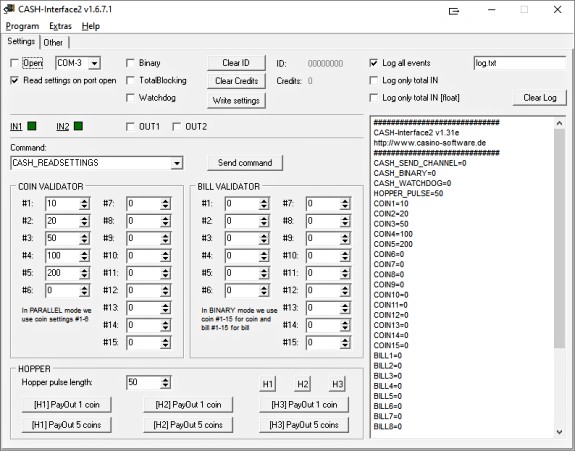
Another possibility to implement the CASH-Interface2 into own projects is to use the demo project. The CI2.EXE sends a WM_CopyData Message with every event in the format ID,DATE,TIME,CHANNEL,VALUE which can be received from your software. Additionally the program writes a logfile LOG.TXT in the same format, which can be evaluated externally from your software. To load CASH.EXE on system run just put a shortcut into the autostart folder. Simply activate the HIDE checkbox to run it invisible in the background. Change settings for coins and banknotes If the connection to the CASH-Interface has been established, means the Com port is open, all settings have been read on port open from the CASH-Interface2 board and are shown in the software. Now the values for coins (COIN VALIDATOR) and banknotes (BILL VALIDATOR) can be set to any value of your needs. Hint: In PARALLEL mode we only use coin 1-6 settings, this is shown in the software, too! Now just set the coin or bill value for the corresponding channel. Example: The coin validator has been set up to this, #1 - 10 Cent, #2 - 20 Cent, #3 - 50 Cent, #4 - 1 Euro, #5 - 2 Euro, so set for #1: 10, for #2: 20, for #3: 50, for #4: 100 and for #5: 200. Finally all settings must be sent to the board by pressing the "Write settings" button. To verify the new settings are really stored correctly onto the CASH-Interface2, just send the command CASH_READSETTINGS by the "Send command" button, the CASH-Interface2 sends then all settings to the PC again. If "Log all events" is active all data is shown in the log. Alternatively close the Com Port and open it again, with activated "Read settings on port open" the settings are read again from the CASH-Interface2. Commands Commands to the CASH-Interface2 have to end with a "carriage return". In computing, the carriage return (CR) hexadezimal 0D or dezimal 13, is one of the control characters in ASCII code. The CASH-Interface2 detects a byte with the value #13 ($0D) as command end. Example: CASH_READSETTINGS$0D All data from the CASH-Interface2 ends with a "carriage return" and "line feed" (CRLF = Enter). This way you can detect the end of the data. When you receive the bytes $0D$0A all data has been received and the data can be processed. The communication from and to the CASH-Interface2 can be tested with a terminal program. COM port settings: Baud 19200, Data bits 8, Parity none, Stop bits 1, Handshaking none
COMMANDS:

- CASH_READ
    read state of all channels + NV busy signal
    Example: "CASH_READ"
    Returns: "CASH_READ=n"
    bit 0 = channel 1
    bit 1 = channel 2
    bit 2 = channel 3
    bit 3 = channel 4
    bit 4 = channel 5
    bit 5 = channel 6 or coin validator binary line
    bit 6 = NV busy
    bit 7 = power supply ok

- CASH_TOTALBLOCKING 0|1
    set the totalblocking line to enable or disable acceptance of cash
    "CASH_TOTALBLOCKING 0" enables acceptance of cash
    "CASH_TOTALBLOCKING 1" disables acceptance of cash
    Example: "CASH_TOTALBLOCKING 0" or "CASH_TOTALBLOCKING 1"
    Returns: "CASH_TOTALBLOCKING=n". On Error "ERROR".

- CASH_BINARY 0|1
    sets the protocol of the connected coin and bill validator
    "CASH_BINARY 0" the coin and bill validator work with PARALLEL protocol
    "CASH_BINARY 1" the coin and bill validator work with BINARY protocol
    Example: "CASH_BINARY 0" or "CASH_BINARY 1"
    Returns: "CASH_BINARY=n". On Error "ERROR".

- CASH_IN1
    read state of external input IN1
    Example: "CASH_IN1"
    Returns: "CASH_IN1=n" state of the external input IN1
    0 = IN1 is LOW
    1 = IN1 is HIGH

- CASH_IN2
    read state of external input IN2
    Example: "CASH_IN2"
    Returns: "CASH_IN2=n" state of the external input IN2
    0 = IN2 is LOW
    1 = IN2 is HIGH

- CASH_OUT1 0|1
    set state of output OUT1
    Example: "CASH_OUT1 0" set OUT1 to LOW
    Example: "CASH_OUT1 1" set OUT1 to HIGH
    Returns: "CASH_OUT1=n". On Error "ERROR".

- CASH_OUT2 0|1
    set state of output OUT2
    Example: "CASH_OUT2 0" set OUT2 to LOW
    Example: "CASH_OUT2 1" set OUT2 to HIGH
    Returns: "CASH_OUT2=n". On Error "ERROR".

- CASH_READSETTINGS
    read all settings from the CASH-Interface2
    Example: "CASH_READSETTINGS"
    Returns: all stored settings

    #############################
    CASH-Interface2 v1.35g
    http://www.casino-software.de
    #############################
    CASH_SEND_CHANNEL=0
    CASH_BINARY=0
    CASH_WATCHDOG=0
    HOPPER_PULSE=50
    COIN1=10
    COIN2=20
    COIN3=50
    COIN4=100
    COIN5=200
    COIN6=0
    COIN7=0
    COIN8=0
    COIN9=0
    COIN10=0
    COIN11=0
    COIN12=0
    COIN13=0
    COIN14=0
    COIN15=0
    BILL1=500
    BILL2=1000
    BILL3=2000
    BILL4=5000
    BILL5=0
    BILL6=0
    BILL7=0
    BILL8=0
    BILL9=0
    BILL10=0
    BILL11=0
    BILL12=0
    BILL13=0
    BILL14=0
    BILL15=0
    #############################

- HOPPER <hopper number> <coins>
    pay out a coin with specific hopper
    "HOPPER 1 1" pay out 1 coin with hopper 1
    "HOPPER 1 5" pay out 5 coins with hopper 1
    "HOPPER 2 1" pay out 1 coin with hopper 2
    "HOPPER 2 5" pay out 5 coins with hopper 2
    "HOPPER 3 1" pay out 1 coin with hopper 3
    "HOPPER 3 5" pay out 5 coins with hopper 3
    Example: "HOPPER 1 1"
    Returns: "HOPPER_n=x". On Error "ERROR".

- HOPPER1_EMPTY
    read state of hopper1 empty detection
    Example: "HOPPER1_EMPTY"
    Returns: "HOPPER1_EMPTY=n" state of the hopper1 empty signal
    0 = no hopper1 empty signal detected, hopper is not empty
    1 = hopper1 empty signal detected, hopper is empty

- HOPPER2_EMPTY
    read state of hopper2 empty detection
    Example: "HOPPER2_EMPTY"
    Returns: "HOPPER2_EMPTY=n" state of the hopper2 empty signal
    0 = no hopper2 empty signal detected, hopper is not empty
    1 = hopper2 empty signal detected, hopper is empty

- HOPPER3_EMPTY
    read state of hopper3 empty detection
    Example: "HOPPER3_EMPTY"
    Returns: "HOPPER3_EMPTY=n" state of the hopper3 empty signal
    0 = no hopper3 empty signal detected, hopper is not empty
    1 = hopper3 empty signal detected, hopper is empty

- HOPPER_FULL
    read state of hopper full detection
    Example: "HOPPER_FULL"
    Returns: "HOPPER_FULL=n" state of the hopper full signal
    0 = no hopper full signal detected, hopper is not full
    1 = hopper full signal detected, hopper is full
    Hint: The hopper full signal is normally used to control the coin sorter
          via coin #5 line. To activate this the jumper JP1.1 must be set.

- HOPPER_PULSE <pulse length in ms>
    sets the hopper pulse length in milli seconds. Default is 100.
    Example: "HOPPER_PULSE 100"
    Returns: "HOPPER_PULSE=n". On Error "ERROR".

- HOPPER1_ON <Optocoupler 1 ON>
    sets the optocoupler 1. Pin7 is GND.
    If you do not use a hopper you can use this as an output.
    The optocoupler is able to switch 80mA current.
    Example: "HOPPER1_ON"
    Returns: "HOPPER1_ON". On Error "ERROR".

- HOPPER1_OFF <Optocoupler 1 OFF>
    resets the optocoupler 1. Pin7 is not GND.
    Example: "HOPPER1_OFF"
    Returns: "HOPPER1_OFF". On Error "ERROR".

- HOPPER2_ON <Optocoupler 2 ON>
    sets the optocoupler 2. Pin7 is GND.
    If you do not use a hopper you can use this as an output.
    The optocoupler is able to switch 80mA current.
    Example: "HOPPER2_ON"
    Returns: "HOPPER2_ON". On Error "ERROR".

- HOPPER2_OFF <Optocoupler 2 OFF>
    resets the optocoupler 2. Pin7 is not GND.
    Example: "HOPPER2_OFF"
    Returns: "HOPPER2_OFF". On Error "ERROR".

- HOPPER3_ON <Optocoupler 3 ON>
    sets the optocoupler 3. Pin7 is GND.
    If you do not use a hopper you can use this as an output.
    The optocoupler is able to switch 80mA current.
    Example: "HOPPER3_ON"
    Returns: "HOPPER3_ON". On Error "ERROR".

- HOPPER3_OFF <Optocoupler 3 OFF>
    resets the optocoupler 3. Pin7 is not GND.
    Example: "HOPPER3_OFF"
    Returns: "HOPPER3_OFF". On Error "ERROR".

- CASH_COIN <channel> <value>
    sets the channel value for a coin
    "CASH_COIN 1 1" sets coin1 to 1
    "CASH_COIN 1 10" sets coin1 to 10
    "CASH_COIN 2 1" sets coin2 to 1
    "CASH_COIN 2 10" sets coin2 to 10
    Example: "CASH_COIN 1 1"
    Returns: "CASH_COIN_n=x". On Error "ERROR".

- CASH_BILL <channel> <value>
    sets the channel value for a bill
    "CASH_BILL 1 1" sets bill1 to 1
    "CASH_BILL 1 10" sets bill1 to 10
    "CASH_BILL 2 1" sets bill2 to 1
    "CASH_BILL 2 10" sets bill2 to 10
    Example: "CASH_BILL 1 1"
    Returns: "CASH_BILL_n=x". On Error "ERROR".

- CASH_WATCHDOG 0|1
    disable acceptance of cash if there is no command received
    within 60sec
    "CASH_WATCHDOG 0" disables the watchdog
    "CASH_WATCHDOG 1" enables the watchdog
    Example: "CASH_WATCHDOG 0" or "CASH_WATCHDOG 1"
    Returns: "CASH_WATCHDOG=n". On Error "ERROR".

- CASH_WATCHDOG_RESET
    Reset the internal watchdog timer.
    Should be sent from the host application around every 50 seconds.
    Watchdog timeout is 60 seconds.

- CASH_SEND_CHANNEL 0|1
    Send the channel number with the IN=n credits message
    "CASH_SEND_CHANNEL 0" disables sending channel number
    Message will be: IN=n
    "CASH_SEND_CHANNEL 1" enables sending channel number
    Message will be: IN=n,channel
    Example: "CASH_SEND_CHANNEL 1" or "CASH_SEND_CHANNEL 1"
    Returns: "CASH_SEND_CHANNEL=n". On Error "ERROR".

- CASH_CLEARBUFFER
    Clear serial input and output buffer

- Wrong command
    Returns: "UNKNOWN_COMMAND="
IN1+2 connection IN1 + IN2 provides an ACTIVE LOW input designed as follows: 
REL connection REL provides a potential-free relay output designed as follows: The on board relays max. voltage is 200V, max. switching load is 15W. 
OUT2 connection OUT 2 provides a +12V output designed as follows: The transistor max. current is 0,5A. 
CI2 dimensions 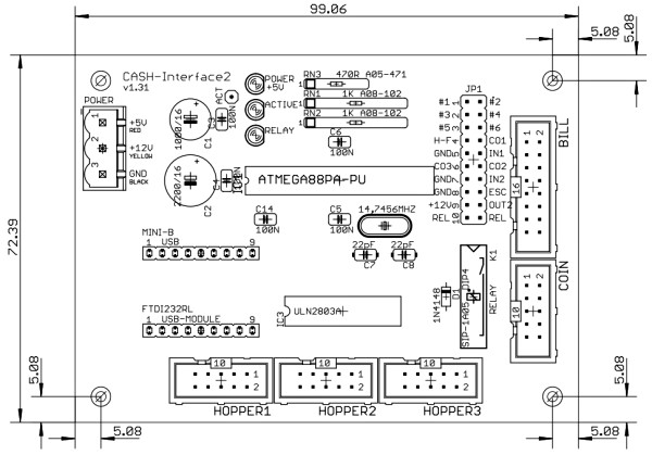
Getting started / testing Connect the CASH-Interface2 via a USB cable to your PC. Connect the coin and bill validator via the flat ribbon cable to the CASH-Interface2. Connect the 12V DC power supply, ensure that the poles are connected correctly! By use of an external power supply the power supply should min. support 12V/1,5 amps current for the bill validator. For a coin validator the power supply should min. support 12V/0,5 amps current. To supply both devices you need a power supply with at least 12V/2A. On the CASH-Interface2 the green LED indicates the +12V power supply is ok. To test the CASH-Interface2 please use the Delphi example program ci2.exe. The example program can be found in the folder /delphi/example/ci2.exe or a shortcut in the Windows startmenu, all programs, CI2, Example. Start the example program and set the right com port. Activate the "Open" checkbox. The connection to the CASH-Interface2 is open now and commands can be sent and data received. Select the command "CASH_READSETTINGS" and send it to the CASH-Interface2 with the "Send command" button. The CASH-Interface2 answers to this command with sending all stored settings. Now insert a coin or a bill. The CASH-Interface2 sends for every accepted coin or bill a string in the format: IN=n Problems Having problems work thru this checklist, this should help to fix your issues! • If the COM port is open, the answer from the board with all settings must appear in the log. If not, there is something wrong with the connection to the CASH-Interface2, or simply the wrong COM port setting. Important: Check tight cable connections and the power supply is connected correctly. The correct COM port number can be found in the Windows device manager, see Ports (COM & LPT). • Check all cables if they fit tight. • Remove all extension cables, e.g. USB extension cord or USB hub. • Disconnect the power cable on the CI2, then connect it again. • If the connection to the CASH-Interface2 is working, but no cash is accepted, maybe the TotalBlocking function in the software is activated. The yellow LED on the board must lit to accept money. If coins or bills are rejected with illuminated ACTIVE LED, either the cable or the cash device itself is broken. • Use a different USB plug on the PC, and replace all cables if problems still appear. • A COM port can be opened only once, so be sure the COM port is not open by an other application. • Be sure the coin validator is placed horizontal so the device can measure correctly. • Check the log file for error messages, this gives you hints what exactly is the problem. • Check the power supply for the board. Measure the +12V (green LED) with a Voltmeter. • Sometimes it helps to completely uninstall the software via Windows control panel, and do a fresh install. Doing this visit the CI2 website to download the latest version. Support For your inquiry please use our online E-Mail form. Copyright © by bksoft |