|
Coin validator PC adapter v1.11 Universal COIN Interface With the coin validator PC adapter you can connect "pulse mode" coin validators of the type NRI G13 - NRI G18 - NRI G40 - EMP800 - RM5 - MARS - MONEY CONTROLS C120 - AZKOYEN - FAGE - ICT - APEX - MATRIX - VECTOR - MEI and others easily and economically to the USB port (with USB to serial converter) or to the serial port of the PC. You can connect ALL devices which are supporting the PULSE mode. 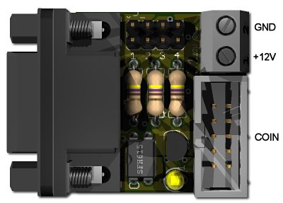
Features - Operation of a "pulse mode" coin validator on the USB port (with USB to serial converter) or on the serial port. - Power supply 12V up to 24V DC (depends on the coin validator) - Acceptance of money is controllable (TOTALBLOCKING / INHIBIT) - Very easy integration to your own projects, e.g.: - via coin.exe using logfile monitoring - via coin.exe using WMCopyData - via coin.exe using ShellExecute - via your own COM port programming - via our KIOSK TIMER SOFTWARE Supported devices Coin validators of the type: RM5, NRI G13/G18, NRI G40, EMP, MARS, MONEY CONTROLS C120, AZKOYEN, FAGE, ICT, APEX, MATRIX, VECTOR, MEI or other. You can connect ALL devices which are supporting PULSE mode. Connection Connect the coin validator PC adapter with a USB to Serial converter or serial cable to the PC. Supply the interface with a direct current voltage of 12V to the terminal (+12V/0V). Ensure that the poles are connected correctly and the power supply is strong enough. A coin validator can take up to 500 mA of current. For a 24V coin validator just connect 24V DC. The connection of the coin validator (e.g. NRI G13) is made by a 10 pole flat ribbon cable to the 10 pole plug. Occupation of the 10 pole plug (NRI G13 compatible): 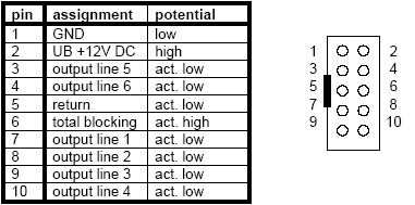
Jumper Instead of use the PC's COM port its possible to wire the application via the jumpers to external electronics. 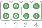
JP1.1 - Opto out, pin1=Collector, pin2=Emitter JP1.2 - +12V to Opto Collector, means +12V signal on JP1.1 pin2 JP1.3 - GND to Opto Emitter, means GND signal on JP1.1 pin1 JP1.4 - GND to COIN pin 6, means all time INHIBIT Jumper settings example: � To have +12V signal set JP1.2 and grab output at JP1.1 pin2 � To have GND signal set JP1.3 and grab output at JP1.1 pin1 The signal length is exactly as long as the coin validator signal and is normally 100ms. For example, a timer board could be controlled with this signal. Devices settings The coin validator has to work in PULSE mode protocol. That means all coin signals are indicated on the "output line 1" of the coin validator. The channels of the coin validator have to be programmed accordingly. The value of the signal becomes the smallest coin value (10 cent in the example)). The coin validador then triggers the number of signals by coin. You can get the software and cable to reprogram the respective device from the manufacturer, or just choose the desired channel occupancy with your order. Example coin validator (PULSE Mode): Coin validator channel 1 = 10 Cent coin (1 pulse on output line1) Coin validator channel 2 = 20 Cent coin (2 pulses on output line1) Coin validator channel 3 = 50 Cent coin (5 pulses on output line1) Coin validator channel 4 = 1 Euro coin (10 pulses on output line1) Coin validator channel 5 = 2 Euro coin (20 pulses on output line1) Coin validator channel 6 = token (50 pulses on output line1) Programming The software integration into your projects is done via standard COM port commands or with the free COIN software (COIN.EXE). The source code of the COIN.EXE is available as a Delphi project in the corresponding subdirectory. coin.exe 
All you need is a COM port component, e.g. https://bitbucket.org/wpostma/tcomport2010 that allows you to access the COM port. By opening the com port you have to set the DTR line to HIGH. Then the coin validator signals are routed thru the coin validator PC adapter to the CTS line of the COM port, so you only have to monitor the CTS line and add credits on every pulse. To enable cash acceptance set the RTS line to HIGH (means TOTALBLOCKING / INHIBIT gets LOW). The TOTALBLOCKING / INHIBIT state is indicated by the LED. Another possibility to implement the coin validator PC adapter into own projects is to use the demo project COIN.EXE. The COIN.EXE writes a log file for every event. Name and location of the log file can be freely set, by default this is "c:\user\USERNAME\AppData\Roaming\bksoft\coinadapter\credits.txt". The content of the log file can be configured, for example every event creates a log entry with ID, DATE, TIME, CHANNEL, VALUE. Or the log file just contains the current credits, this can be evaluated externally from another software. Additionally the COIN.EXE sends a WM_CopyData Message with every event in the format ID, DATE, TIME, CHANNEL, VALUE which can be received from your software. The COIN.EXE can also execute and run a program or script on coin in, e.g. a batch file which then passes the credits to your software. To load COIN.EXE on system run just activate the "Autostart on Windows boot", this way the program runs invisible in the background. Getting started / testing Connect the coin validator PC adapter via a USB to serial converter to the USB port or directly to a COM port of the PC. Connect the coin validator via the flat ribbon cable to the coin validator PC adapter. Connect the 12V power supply. If you use the PC power supply use the YELLOW cable for +12V and the BLACK cable beside it for 0V. Ensure that the poles are connected correctly and the power supply is strong enough. By use of an external power supply the power supply should min. support 12 V/0.5 amps current for the coin validator. To test the coin validator PC adapter please use the Delphi example program COIN.EXE. The example program can be found in the folder /delphi/coin.exe or a shortcut in the Windows startmenu, all programs, Coin validator PC adapter, COIN Example. Start the example program and set the correct com port. Set up the coin validator pulse value, e.g. 10 for 10 Cent. Then activate the "Poll" checkbox. If TOTALBLOCKING is not selected, the LED signals readiness to accept money. Now insert a coin. The signal from the coin validator is shown for the duration time of the signal and appears in the logfile. Support For your inquiry please use our online E-Mail Form. © by bksoft |