|
CASH-Interface v4.05 Universal CASH Interface Features - Simultaneous operation of a coin and bill validator on the serial port. - The interface is monitoring six channels + power supply and gives back the state in form of a BYTE. Using BINARY Mode there are i.e. 15 different bills and 31 different coins possible at the same time. - The pinning of the connectors are designed for coin acceptors of the type NRI G13/G18, EMP, RM5X00, MONEY CONTROLS C120 and for bill acceptors of the type NV7/NV8/NV9/NV10 - The devices are disabled until the software activates them. - With the jumpers single notes can be enabled or disabled for accepting (inhibit). - Bill JAMMED detection via the validator's BUSY signal. - 2 extra free usable inputs, for example to monitor external credit signals, have different bill/coin settings, key switch, wake up line, ... 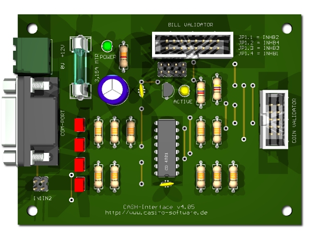
Supported devices Coin validators of the type: RM5, NRI G13/G18, NRI G40, EMP, MARS, MONEY CONTROLS C120, AZKOYEN, FAGE, ICT Bill validators of the type: NV4/NV7/NV8/NV9/NV10 (SMILEY), JCM, GBAI/GBAII, MEI, APEX, MATRIX, VECTOR You can also connect ALL devices which are supporting PARALLEL, PULSE or BINARY mode. Connection Connect the interface with a serial cable to the PC. Supply the interface with a direct current voltage of 12V to the terminal (+12V/0V). Ensure that the poles are connected correctly. Be sure to take the precaution of making sure the power supply is strong enough. A bill validator can take up to 1500 mA and a coin acceptor up to 500mA of current. The connection of the coin acceptor (e.g. NRI G13) is made by a 10 pole flat ribbon cable to the plug marked with COIN VALIDATOR. Occupation of the 10 pole plug (NRI G13 compatible): 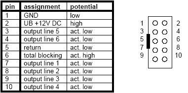
The connection of the bill validator (e.g. NV7/8/9/10) is made by a 16 pole flat ribbon cable to the plug marked with BILL VALIDATOR. Occupation of the 16 pole plug (NV7/8/9/10 compatible):
If you want to connect a other bill validator than NV7/8/9/10 you need to assemble a adapter cable with the above occupancy. On request we also supply you with fitting adapter cables. Devices settings For simultaneous operation of coin and bill acceptor we suggest this configuration: Bill validator and coin validator in BINARY mode. You have to adjust the channels of coin and bill validator accordingly. You can get the software and cable to reprogram the respective device from the manufacturer, or just choose the desired channel occupancy with your order. Using only one device, the valency of the channels can be assigned by the software. That means there is no need of reprogramming the device's! Example for connecting a bill and coin acceptor (bill acceptor BINARY mode, coin acceptor BINARY mode): Channel 1-4 = bill acceptor binary coded value (up to 15 different bills) Channel 1 = bill acceptor 5 Euro bill Channel 2 = bill acceptor 10 Euro bill Channel 1+2 = bill acceptor 20 Euro bill Channel 3 = bill acceptor 50 Euro bill Channel 1+3 = bill acceptor 100 Euro bill Channel 2+3 = bill acceptor 200 Euro bill Channel 1+2+3 = bill acceptor 500 Euro bill and so on up to 15 different bills possible... Channel 1-5 + 6 = coin acceptor binary coded value (up to 31 different coins) Channel 1+6 = coin acceptor 1 Cent coin Channel 2+6 = coin acceptor 2 Cent coin Channel 1+2+6 = coin acceptor 5 Cent coin Channel 3+6 = coin acceptor 10 Cent coin Channel 1+3+6 = coin acceptor 20 Cent coin Channel 2+3+6 = coin acceptor 50 Cent coin Channel 1+2+3+6 = coin acceptor 1 Euro coin Channel 4+6 = coin acceptor 2 Euro coin and so on up to 31 different coins possible... Example for connecting only a coin acceptor (PARALLEL mode): Channel 1 = coin acceptor 10 Cent coin Channel 2 = coin acceptor 20 Cent coin Channel 3 = coin acceptor 50 Cent coin Channel 4 = coin acceptor 1 Euro coin Channel 5 = coin acceptor 2 Euro coin Channel 6 = coin acceptor token Example for connecting only a coin acceptor (BINARY mode): Channel 1-3 = binary coded value (up to 7 different coins) Channel 1-4 = binary coded value (up to 15 different coins) Channel 1-5 = binary coded value (up to 31 different coins) Channel 1-6 = binary coded value (up to 63 different coins) Channel 1 = coin acceptor 1 Cent coin Channel 2 = coin acceptor 2 Cent coin Channel 1+2 = coin acceptor 5 Cent coin Channel 3 = coin acceptor 10 Cent coin Channel 1+3 = coin acceptor 20 Cent coin Channel 2+3 = coin acceptor 50 Cent coin Channel 1+2+3 = coin acceptor 1 Euro coin Channel 4 = coin acceptor 1 Euro coin Example for connecting only a bill acceptor (PARALLEL mode): Channel 1 = bill acceptor 5 Euro bill Channel 2 = bill acceptor 10 Euro bill Channel 3 = bill acceptor 20 Euro bill Channel 4 = bill acceptor 50 Euro bill Example for connecting only a bill acceptor (PULSE mode): Channel 1 = bill acceptor 5 Euro bill (1 impulse) Channel 2 = bill acceptor 10 Euro bill (2 impulses) Channel 3 = bill acceptor 20 Euro bill (4 impulses) Channel 4 = bill acceptor 50 Euro bill (10 impulses) We do not recommend the PULSE mode, because it takes too much time to get all impulses! It is better to use the device in PARALLEL mode to get only 1 impulse for each bill. Example for connecting only a bill acceptor (BINARY mode): Channel 1-3 = binary coded value (up to 7 different bills) Channel 1-4 = binary coded value (up to 15 different bills) Channel 1-5 = binary coded value (up to 31 different bills) Channel 1-6 = binary coded value (up to 63 different bills) Channel 1 = bill acceptor 5 Euro bill Channel 2 = bill acceptor 10 Euro bill Channel 1+2 = bill acceptor 20 Euro bill Channel 3 = bill acceptor 50 Euro bill Channel 1+3 = bill acceptor 100 Euro bill Channel 2+3 = bill acceptor 200 Euro bill Channel 1+2+3 = bill acceptor 500 Euro bill Example for connecting a bill and coin acceptor (PARALLEL mode): Channel 1 = bill acceptor 5 Euro bill Channel 2 = bill acceptor 10 Euro bill Channel 3 = bill acceptor 20 Euro bill Channel 4 = bill acceptor 50 Euro bill Channel 5 = coin acceptor 1 Euro coin Channel 6 = coin acceptor 2 Euro coin Example for connecting a bill and coin acceptor (bill acceptor PULSE mode, coin acceptor PARALLEL mode): Channel 1 = bill acceptor 5 Euro bill (1 impulse) Channel 1 = bill acceptor 10 Euro bill (2 impulses) Channel 1 = bill acceptor 20 Euro bill (4 impulses) Channel 1 = bill acceptor 50 Euro bill (10 impulses) Channel 2 = coin acceptor 10 Cent coin Channel 3 = coin acceptor 20 Cent coin Channel 4 = coin acceptor 50 Cent coin Channel 5 = coin acceptor 1 Euro coin Channel 6 = coin acceptor 2 Euro coin Example for connecting a bill and coin acceptor (coin acceptor BINARY mode, bill acceptor PULSE mode): Channel 1 = bill acceptor 5 Euro bill (1 impulse) Channel 1 = bill acceptor 10 Euro bill (2 impulses) Channel 1 = bill acceptor 20 Euro bill (4 impulse) Channel 1 = bill acceptor 50 Euro bill (10 impulse) Channel 1 = bill acceptor 100 Euro bill (20 impulse) Channel 1 = bill acceptor 200 Euro bill (40 impulse) Channel 1 = bill acceptor 500 Euro bill (100 impulse) Channel 2 = coin acceptor 1 Cent coin Channel 3 = coin acceptor 2 Cent coin Channel 2+3 = coin acceptor 5 Cent coin Channel 4 = coin acceptor 10 Cent coin Channel 2+4 = coin acceptor 20 Cent coin Channel 3+4 = coin acceptor 50 Cent coin Channel 2+3+4 = coin acceptor 1 Euro coin Channel 5 = coin acceptor 2 Euro coin With the use of coin and bill validator at the same time different protocols can be mixed. PARALLEL, PULSE or BINARY mode should be selected depending on the need of the number of coins and bills to get the optimal channel seizure and speed! We suggest to use BINARY mode for both devices. Programming The software integration into your projects is done via the CASH.DLL. You can find example projects for Delphi, Visual Basic 6 and Visual Basic .NET in the corresponding subdirectory. The Delphi project is also avariable as ready compiled file with the name CASH.EXE The CASH.DLL was programmed with Delphi, therefore the example application for Delphi is the most detailed. See directory /delphi/example/cash.exe cash.exe 
Another possibility to implement the CASH interface into own projects is to use the demo project. The CASH.EXE sends a WM_CopyData Message with every event in the format ID,DATE,TIME,CHANNEL,VALUE which can be received from your software. Additionally the program writes a logfile LOG.TXT in the same format, which can be evaluated externally from your software. To load CASH.EXE on system run just put a shortcut into the autostart folder. Simply activate the HIDE checkbox to run it invisible in the background. Getting started / testing Connect the CASH-Interface via the 9pol. com cable to the serial port on your PC. Connect the coin and bill validator via the flat ribbon cable to the CASH-Interface. Connect the 12V power supply. If you use the PC power supply use the YELLOW cable for +12V and the BLACK cable beside it for 0V. Ensure that the poles are connected correctly! By use of an external power supply the power supply should min. support 12 V/1.5 amps current for the bill validator. For a coin validator the power supply should min. support 12 V/0.5 amps current. To supply both devices you need a power supply with at least 12V/2A. On the CASH-Interface the green LED indicates the power supply is ok. To test the CASH-Interface please use the Delphi example program cash.exe. The example program can be found in the folder /delphi/example/cash.exe or a shortcut in the Windows startmenu, all programs, CASH.DLL, CASH Example. Start the example program and set the right com port. Select the mode your devices are working with, i.e. BINARY for binary mode, or BINARY unchecked for PARALLEL or PULSE mode. The coin/bill values can be set, i.e. channel1 to 500 for a 5 EUR note. For the binary mode you have to set the coin/bill values in the "CASH-Interface BINARY Settings" tab. Now activate the "Poll" checkbox. The power indicator should lit and the value for CASH_READ must be 128. On the CASH-Interface the YELLOW LED is lit and signals the coin and bill devices are enabled to accept money. Throw in a coin or insert a bill. The signal from the coin or bill acceptor is shown for the duration time of the signal on the corresponding channel and appears in the logfile. To test the inputs activate the "Poll IN" checkbox and shorten the jumper JP2.1 for IN1 and JP2.2 for IN2. For wiring the inputs IN1 + IN2 you may use only dry contact / potential-free contact like a switch or relay contact. The monitoring of the inputs is only working if the CASH-Interface is ACTIVE! Support For your inquiry please use our online E-Mail Form Copyright © 2009 by bksoft |