|
HOPPER-Interface v3.04 Universal Hopper Interface Features - Connect arbitrary hopper at the serial interface. - The hopper is disabled until the software activates it. - TimeOut supervision, for example if the hopper is empty or on coin jammed. - The connection is designed for hoppers of the type Cube MK2 (driver cable). There is also a 10 pol plug for Azkoyen hoppers. By use of solderless lugs all other hopper types can be attached without any problems, too. - The control is carried out with the CASH.DLL of the CASH-Interface - It is possible to control 2 hoppers. - 1 extra free usable input for example to monitor full or empty state, key switch, wake up line, ... 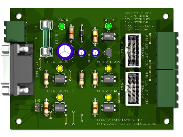
Supported devices Hoppers of the type: Cube Hopper MK2, Universal Hopper MK2, MK3 and MK4, Evolution Hopper, Escendo Escalator Hopper, Excel Hopper, Rode-U-Hopper, Azkoyen Hopper or other that support the PARALLEL mode. Note dispenser of the type: ICT ND-300 , ICT CVD-300 or other that support the HOPPER / PARALLEL mode. You can also connect ALL devices that are supporting PARALLEL mode. Connection Connect the interface with a serial cable to the PC. Supply the interface with a direct current voltage of 12V to the terminal (+12V/0V). Ensure that the poles are connected correctly. Be sure to take the precaution of making sure the power supply is strong enough. A hopper can take up to 2A current and more! Occupation of the 4 pole solderless lugs (Cube MK2 with driver cable): 1 (ORG) = coin signal 2 (WHT) = motor start 3 (RED) = +V (+12V or +24V DC) 4 (BLK) = -V (GND) Occupation of the 10 pole plug (Azkoyen compatible):
If you want to connect other devices than Cube MK2 or Azkoyen you need to assemble a adapter cable with the above occupancy. On request we also supply you with fitting adapter cables. Example for a adapter cable UNIVERSAL HOPPER MK3 / MK4 :
Programming The software integration into your projects is done via the CASH.DLL. You can find example projects for Delphi, Visual Basic 6 and Visual Basic .NET in the corresponding subdirectory. The Delphi project is also avariable as ready compiled file with the name CASH.EXE The CASH.DLL was programmed with Delphi, therefore the example application for Delphi is the most detailed. See directory /delphi/example/cash.exe cash.exe 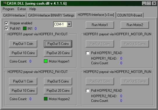
The example program cash.exe may also be used with command line parameters. Therefore cash.exe can payout with hopper 1 or hopper 2 invisible in the background. No reply is available using this method. Call: cash.exe Hoppernumber Coincount Parameter Hoppernumber: 1 = hopper 1, 2 = hopper 2 Parameter Coincount: number of coins example: cash.exe 1 1 payout 1 coin with hopper 1 and close the program. example: cash.exe 1 5 payout 5 coins with hopper 1 and close the program. example: cash.exe 2 1 payout 1 coin with hopper 2 and close the program. example: cash.exe 2 5 payout 5 coins with hopper 2 and close the program. Hints and tips On the circuit board there is a timer that protects the motor for starting up while the com port test on system boot. Without that timer the motor would start and pay out unwanted coins! The timer has a delay of around 2 seconds. As soon as the com port is open it takes these 2 seconds until the HOPPER-Interface signals "Ready". With one HOPPER-Interface you can control 2 hoppers. The payout is done one after each other, i.e. first payout with hopper no.1, when its done payout with hopper no.2. Do not payout with 2 hoppers at the same time. The cube hopper MK2 and Azkoyen hopper U-II can work with either 12V or 24V DC power supply. MK3 and MK4 hopper need 24V DC power supply. Getting started / testing Connect the HOPPER-Interface via the 9pol. com cable to the serial port on your PC. Connect the hopper via the flat ribbon cable or solderless lugs to the HOPPER-Interface. Connect the 12V or 24V power supply. If you use the PC power supply use the YELLOW cable for +12V and the BLACK cable beside it for 0V. Ensure that the poles are connected correctly! By use of an external power supply the power supply should min. support 12 V/2 amps current for the hopper. On the HOPPER-Interface the green LED indicates the power supply is ok. To test the HOPPER-Interface please use the Delphi example program cash.exe. The example program can be found in the folder /delphi/example/cash.exe or a shortcut in the Windows startmenu, all programs, CASH.DLL, CASH Example. Start the example program and set the right com port. Click on the Run Motor1 or Run Motor2 button. The hopper should now run for the time you press the button. With the example program you can test now the payout with the function HOPPERx_PAYOUT or HOPPERx_MOTOR_RUN and HOPPERx_READ. To test the input activate the "Poll IN1" checkbox and shorten the jumper JP1.1 for IN1. For wiring the input IN1 you may use only dry contact / potential-free contact like a switch or relay contact. Support For your inquiry please use our online E-Mail Form Copyright © 2009 by bksoft |
